dienelectrics@gmail.com
 0909186879 dienelectrics@gmail.com

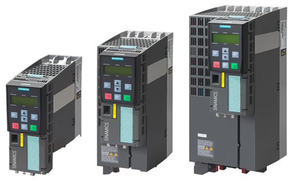
The Power Module contains:
As standard, the Power Module has the following interfaces:
- 1 line supply connection
DRIVE-CLiQ cables for connections to further DRIVE-CLiQ devices can be ordered pre-assembled and cut to length as required (see Section Supplementary system components → Signal cables).
The scope of supply of the Power Modules includes:
- 1 DRIVE-CLiQ cable for connection to the Control UnitThe Power Module communicates with the CU320‑2 Control Unit via DRIVE-CLiQ and receives its control information via this route.

Connection example of a Power Module
|
Line voltage |
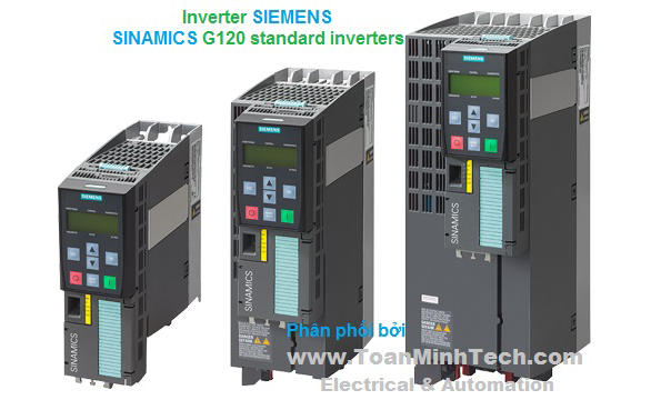
Power Modules |
|||||
|---|---|---|---|---|---|---|
|
|
6SL3310-1GE32-1AA3 |
6SL3310-1GE32-6AA3 |
6SL3310-1GE33-1AA3 |
6SL3310-1GE33-8AA3 |
6SL3310-1GE35-0AA3 |
|
|
Type rating |
|
|
|
|
|
|
|
kW |
110 |
132 |
160 |
200 |
250 |
|
kW |
90 |
110 |
132 |
160 |
200 |
|
hp |
150 |
200 |
250 |
300 |
400 |
|
hp |
150 |
200 |
200 |
250 |
350 |
|
Output current |
|
|
|
|
|
|
|
A |
210 |
260 |
310 |
380 |
490 |
|
A |
205 |
250 |
302 |
370 |
477 |
|
A |
178 |
233 |
277 |
340 |
438 |
|
Input current |
|
|
|
|
|
|
|
A |
229 |
284 |
338 |
395 |
509 |
|
A |
335 |
410 |
495 |
606 |
781 |
|
A |
0.8 |
0.8 |
0.9 |
0.9 |
0.9 |
|
Minimum short-circuit current 6) |
A |
3000 |
3600 |
4400 |
4400 |
8000 |
|
Power loss, max. 7) |
|
|
|
|
|
|
|
kW |
2.4 |
3.2 |
3.9 |
4.3 |
5.6 |
|
kW |
2.6 |
3.3 |
4.4 |
4.9 |
6.1 |
|
Cooling air requirement |
m3/s |
0.17 |
0.23 |
0.36 |
0.36 |
0.36 |
|
Cable length, max. between Power Module and motor 8) |
|
|
|
|
|
|
|
m |
300 |
300 |
300 |
300 |
300 |
|
m |
450 |
450 |
450 |
450 |
450 |
|
Degree of protection |
|
IP20 |
IP20 |
IP20 |
IP20 |
IP20 |
|
Sound pressure level LpA (1 m) at 50/60 Hz |
dB |
64/67 |
64/67 |
69/73 |
69/73 |
69/73 |
|
Line connection U1, V1, W1 |
|
M10 screw |
M10 screw |
M10 screw |
M10 screw |
M10 screw |
|
mm2 |
2 × 185 |
2 × 185 |
2 × 240 |
2 × 240 |
2 × 240 |
|
Motor connection U2/T1, V2/T2, W2/T3 |
|
M10 screw |
M10 screw |
M10 screw |
M10 screw |
M10 screw |
|
mm2 |
2 × 185 |
2 × 185 |
2 × 240 |
2 × 240 |
2 × 240 |
|
PE1/GND connection |
|
M10 screw |
M10 screw |
M10 screw |
M10 screw |
M10 screw |
|
mm2 |
2 × 185 |
2 × 185 |
2 × 240 |
2 × 240 |
2 × 240 |
|
PE2/GND connection |
|
M10 screw |
M10 screw |
M10 screw |
M10 screw |
M10 screw |
|
mm2 |
2 × 185 |
2 × 185 |
2 × 240 |
2 × 240 |
2 × 240 |
|
Dimensions |
|
|
|
|
|
|
|
mm |
326 |
326 |
326 |
326 |
326 |
|
mm |
1400 |
1400 |
1533 |
1533 |
1533 |
|
mm |
356 |
356 |
545 |
545 |
545 |
|
Weight, approx. |
kg |
104 |
104 |
176 |
176 |
176 |
|
Frame size |
|
FX |
FX |
GX |
GX |
GX |
Note: The power data in hp units is based on the NEC/CEC standards for the North American market.
1) Rated output of a typical 6-pole standard induction motor based on IL or IH for 3 AC 50 Hz 400 V.
2) Rated output of a typical 6-pole standard induction motor based on IL or IH for 3 AC 60 Hz 460 V.
3) The base-load current IL is based on a load cycle of 110% for 60 s or 150% for 10 s with a load cycle duration of 300 s (see Technical specifications → Overload capability).
4) The base-load current IL is based on a load cycle of 150% for 60 s or 160% for 10 s with a load cycle duration of 300 s (see Technical specifications → Overload capability).
5) If the auxiliary supply is to be fed in separately from the load supply, e.g. if the control should be able to continue communication when the line voltage fails.
6) The minimum current required to reliably trigger 3NE1 protective devices.
7) The specified power losses are the maximum values for a utilization of 100%. The values are lower under normal operating conditions.
8) Longer cable lengths for specific configurations are available on request.
|
Line voltage |
Power Modules |
||||
|---|---|---|---|---|---|
|
|
6SL3310-1GE36-1AA3 |
6SL3310-1GE37-5AA3 |
6SL3310-1GE38-4AA3 |
6SL3310-1GE41-0AA3 |
|
|
Type rating |
|
|
|
|
|
|
kW |
315 |
400 |
450 |
560 |
|
kW |
250 |
315 |
400 |
450 |
|
hp |
500 |
600 |
700 |
800 |
|
hp |
350 |
450 |
600 |
700 |
|
Output current |
|
|
|
|
|
|
A |
605 |
745 |
840 |
985 |
|
A |
590 |
725 |
820 |
960 |
|
A |
460 |
570 |
700 |
860 |
|
Input current |
|
|
|
|
|
|
A |
629 |
775 |
873 |
1024 |
|
A |
967 |
1188 |
1344 |
1573 |
|
A |
1 |
1 |
1 |
1.25 |
|
Minimum short-circuit current 6) |
A |
10000 |
10500 |
16000 |
18400 |
|
Power loss, max. 7) |
|
|
|
|
|
|
kW |
7.2 |
8.5 |
9.1 |
12.7 |
|
kW |
8.1 |
9.4 |
10.2 |
14.5 |
|
Cooling air requirement |
m3/s |
0.78 |
0.78 |
0.78 |
1.48 |
|
Cable length, max. between Power Module and motor 8) |
|
|
|
|
|
|
m |
300 |
300 |
300 |
300 |
|
m |
450 |
450 |
450 |
450 |
|
Degree of protection |
|
IP00 |
IP00 |
IP00 |
IP00 |
|
Sound pressure level LpA (1 m) at 50/60 Hz |
dB |
70/73 |
70/73 |
70/73 |
72/75 |
|
Line connection U1, V1, W1 |
|
2 × M12 screws |
2 × M12 screws |
2 × M12 screws |
3 × M12 screws |
|
mm2 |
4 × 240 |
4 × 240 |
4 × 240 |
6 × 240 |
|
Motor connection U2/T1, V2/T2, W2/T3 |
|
2 × M12 screws |
2 × M12 screws |
2 × M12 screws |
3 × M12 screws |
|
mm2 |
4 × 240 |
4 × 240 |
4 × 240 |
6 × 240 |
|
PE1/GND connection |
|
M12 screw |
M12 screw |
M12 screw |
2 × M12 screws |
|
mm2 |
2 × 240 |
2 × 240 |
2 × 240 |
4 × 240 |
|
PE2/GND connection |
|
2 × M12 screws |
2 × M12 screws |
2 × M12 screws |
3 × M12 screws |
|
mm2 |
4 × 240 |
4 × 240 |
4 × 240 |
6 × 240 |
|
Dimensions |
|
|
|
|
|
|
mm |
503 |
503 |
503 |
909 |
|
mm |
1506 |
1506 |
1506 |
1510 |
|
mm |
540 |
540 |
540 |
540 |
|
Weight, approx. |
kg |
294 |
294 |
294 |
530 |
|
Frame size |
|
HX |
HX |
HX |
JX |
Note: The power data in hp units is based on the NEC/CEC standards for the North American market.
1) Rated output of a typical 6-pole standard induction motor based on IL or IH for 3 AC 50 Hz 400 V.
2) Rated output of a typical 6-pole standard induction motor based on IL or IH for 3 AC 60 Hz 460 V.
3) The base-load current IL is based on a load cycle of 110% for 60 s or 150% for 10 s with a load cycle duration of 300 s (see Technical specifications → Overload capability).
4) The base-load current IL is based on a load cycle of 150% for 60 s or 160% for 10 s with a load cycle duration of 300 s (see Technical specifications → Overload capability).
5) If the auxiliary supply is to be fed in separately from the load supply, e.g. if the control should be able to continue communication when the line voltage fails.
6) The minimum current required to reliably trigger 3NE1 protective devices.
7) The specified power losses are the maximum values for a utilization of 100%. The values are lower under normal operating conditions.
8) Longer cable lengths for specific configurations are available on request.
(Nguyễn Thảo Trường - http://DienElectric.com theo Siemens)